State-of-the-art methods for measuring stress in rock can be broken down into the following four groups (see ISRM Suggested Methods for Rock Stress Determination, 1987):
- Stress-relief methods
- Compensation methods with flat jacks
- Methods based on the hard inclusion theory
- Methods based on hydraulic rock fracturing
The group of stress-relief methods makes use of the fact that a loaded body undergoes deformation when the stresses acting on it are removed. Provided the rock's modulus of elasticity and Poisson's ratio are known, it is possible to calculate the stresses from the deformation.
The best known stress-relief method is the doorstopper method. The "doorstopper" is a carrier element fitted with a strain foil gauge rosette. It is stuck in a specific direction on the smooth floor of a borehole using a special setting device guided on a rod. After taking a zero measurement, the measuring surface (i. e. the borehole floor) is overcored and the relief-induced deformations in the face of the relieved core thus formed are determined with a second measurement. Today it is possible to use this method successfully in boreholes down to a depth of around 30 m.
Overcoring stress-relief tests using a triaxial cell follow a similar procedure. Resistance strain gauges or mechanical probes are used to measure the displacement of the borehole wall when it is overcored. Today this method is used at borehole depths of around 150 m.
Stress-relief methods are ideal for determining the absolute value of stresses, but they are less well suited for monitoring changes of rock stress.
Unlike the stress-relief methods, the compensation methods (with flat jacks) do not require any knowledge of the elastic constants of the rock at the point of measurement.
With the compensation method (flat jacks), the deformations arising during an induced (artificial) relief of the rock are reversed by means of a compensation pressure that is applied with suitable loading devices. The stresses needing to be applied are usually equivalent to the original stresses. This method is mostly used in underground cavities, the stress-relief normally being induced by a saw cut.
Methods based on the hard inclusion theory are suitable for measuring stress changes but less suitable for determining absolute stresses.
This method uses transducers with a far higher modulus of elasticity than that of the rock at the measuring point. The procedure is based on the following theoretical relationships:
If a transducer with modulus of elasticity EM > EG is friction-locked in an elastically loaded rock body with modulus of elasticity EG the stress in the transducer will differ from that in the surrounding rock; stress concentrations will arise in the transducer. If the modulus ratio EM/EG is known, the stresses measured in the transducer can be corrected.
Since it is difficult to friction-lock the transducer tight against the rock, these transducers are usually capable of measuring only changes of stress. If such a transducer is used in a viscous or plastically strained rock area there is also a good chance, however, of measuring primary stresses as well. In this case the transducer can be expected to "grow into place" through rock flowage, i. e. the stresses inside the rock gradually build up in the transducer, too. A pronounced hydrostatic state of stress is also likely to result under these conditions from the rock flowage.
Today there are very many well known measuring methods and instruments based on the hard inclusion theory, a large number of them differing only slightly. They can be categorised accordingly in various characteristic groups according to their principle of measured value conversion and measured value transmission:
- Hydraulic measuring principle (pressure pads, pressure cells)
- Electric measuring principle (strain foil gauges, inductive transducers)
- Mechanical measuring principle (vibrating wires, dial gauges)
- Optical measuring principle (photo-elastic materials)
With the hydraulic pressure cells type Glötzl, the pressure inside the pressure pad acts on a membrane, pressing it against a plate with two boreholes so that it closes the holes. A counter-pressure applied through one of the boreholes is increased gradually until the membrane lifts off the plate. When this happens, the two boreholes are in fluidic contact with each other. The lifting of the membrane is accompanied, therefore, by an outflow of pressure medium through the second borehole. The level of counter-pressure required for this to happen equals the pressure acting in the cell. Slight membrane movements are enough to produce a reading. The working action of these pressure cells is accordingly very hard.
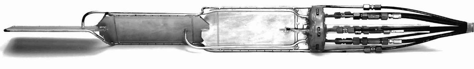
The stressmeter according to Potts consists of two identically shaped, elongated core pieces made of high-strength steel, the one placed on top of the other to form a conical rotary body. Flat slots are cut in the contact faces, creating a narrow gap between the two halves that is filled with an oil/water emulsion. This core piece is pressed in a split sleeve likewise of conical shape on the inside. The two sleeve segments are forced apart and pressed against the borehole wall with defined pre-stressing. A probe screwed to one end of the core piece transforms the pressure acting in the core gap into an electric signal via a membrane fitted with strain foil gauges.
The conical centrepiece is pressed into the sleeve by a small, purpose-designed hydraulic press. This enables the transducer to be inserted in the borehole with defined pre-stressing, thus permitting both increasing and decreasing stresses to be scanned.
As the name suggests, the vibrating wire stressmeter according to Hawkes uses the relationship between a wire's oscillating frequency and its tension as the principle of measurement. The measuring element consists of a thick-walled, hardened steel tube in which a 0.23 mm thick steel wire is clamped vertical to the tube axis. Directly next to the wire is an electromagnetic coil whose function it is to excite the wire vibrations (by current pulsing) as well as to record the frequency of oscillation. The measuring body is flattened at one point of its outer wall in order to mount a pressure plate, which is duly adapted to the radius of the borehole, and a steel wedge.
Using a specially developed hydraulic setting device it is possible to insert and wedge the transducer in a 38 mm borehole. Changes of stress in the borehole surroundings cause a deformation of the tube body and hence a change of wire tension. The resulting change in the wire's oscillating frequency can be read from a cell box that is connected to the transducer by cable. To correct the temperature-related error, the measuring body is fitted with an electric temperature sensor whose signal is also transmitted via cable. The electrical components are sealed, making the measuring element largely insensitive to water. Pressure plates of various sizes are available to match changing strengths of rock.
A transducer developed by Roberts et al is based on photo-elasticity. It consists of a glass cylinder that is illuminated by a small bulb shining through a polarisation filter and a quarter-wave plate. When the transducer is inserted in a borehole, any changes of stress in the rock are transferred to it. If you now examine the glass cylinder through a second polarisation filter, you will see an isochromatic picture from which the state of the stress in the glass - and hence in the surrounding rock - can be derived.
Long-term stability is very good thanks to the properties of the glass. Combined with optical probes or borehole cameras, the transducer may also be used in deeper boreholes.
The installation of such transducers has sometimes proven critical, however, because exact isochromatic pictures are only guaranteed when the bonding is uniform and stress-free.
Only one method has been used to date for measuring absolute stresses at borehole depths of over 200 m - the hydraulic fracturing method. In fact, it has been used at borehole depths of 4000 m and more. Provided certain boundary conditions are fulfilled, it enables complete determination of the stress tensor.
Use of the hydraulic fracturing technique is based on the classical theory that rock at the measuring point is elastic, isotropic and unfractured, and that one of the three main stresses runs in near-vertical direction. A borehole is sunk in this direction to the desired depth and the measuring zone then sealed with one inflatable rubber packer at its upper limit and one at its lower limit.
A liquid (water, oil) is now pumped into this restricted section of the borehole and its pressure gradually increased until there is a sudden loss of liquid and drop of pressure owed to a tension crack in the borehole wall. If the pumping is now discontinued, after a while the crack will stop growing and the pressure will settle at a level just high enough to keep the crack open.
After completely relieving the pressure from the test section, the pressure required to open the crack previously induced in the wall is established. From these pressures and the orientation of the induced crack as indicated by an impression packer it is possible to derive the size and direction of the main orthogonal stresses.
This method was shown to be suitable for use in non-elastic and fractured rock as well (Baumgärtner and Rummel, 1989), and it has also proven to be unnecessary to sink the borehole parallel to one of the main stress directions.
The complete description of Primary Stress Measurements can also be downloaded here as a pdf.