Stress measurements in structures or between structures and rock usually take the form of
- Strain measurements
- Hydraulic pressure cell measurements
- Compensation measurements
Strain measurements are the most frequent source of data in mechanics for strength investigations and stress analyses. With their help it is possible to calculate the loading of structures made of material with a known modulus of elasticity.
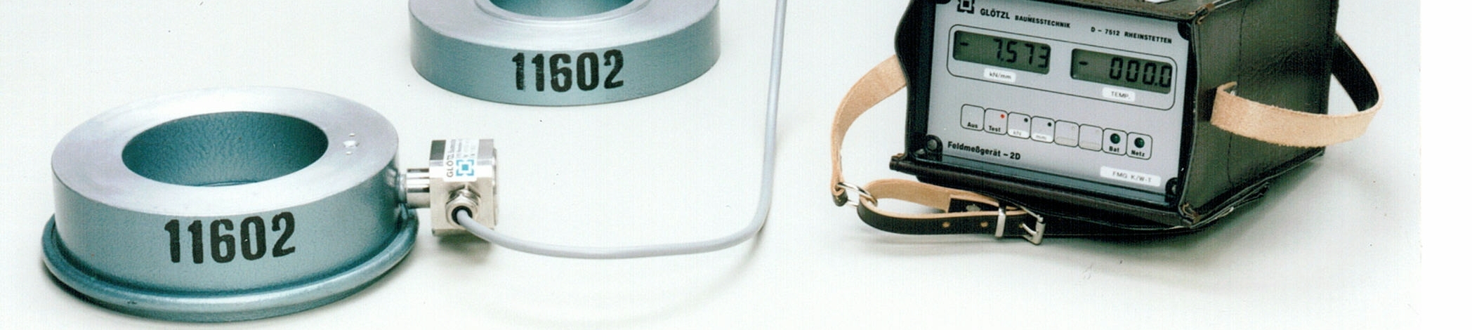
Strain measurements on concrete or steel structures are conducted with measuring sensors based on a strain foil or vibrating wire gauge.
The strain foil gauge is the most frequently used element for measuring strain and other variables derived from it. With this method a component's deformation is transmitted to the measurement grid support of the strain foil gauge, which is bonded or welded on the component, and from there to the measurement grid. This causes the measurement grid's electrical resistance to change; the relationship between strain and change of resistance is known (see Fig. 1).
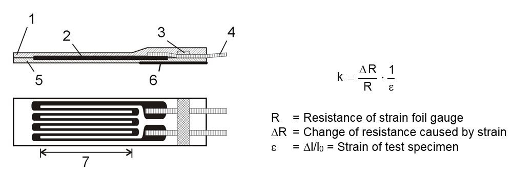
Fig. 1 Design of a strain foil gauge
1 Cover, 2 Measuring grid, 3 Anchorage of connection strips,
4 Connection strips, 5 Support, 6 Reinforcement,
7 Length of measuring grid
As a rule, the change of resistance is converted in a Wheatstone bridge circuit into a proportional electrical voltage and then amplified as much as is required for the operation of recording units or for the triggering of control routines.
Special care is needed when fastening the strain foil gauge to the measurement object, e. g. by bonding. Measuring points must be specially prepared and steps taken to protect the strain foil gauge from dust, moisture and mechanical damage. This is not always possible on a construction site, so special strain sensors have been developed for taking measurements on steel components, e. g. tunnel arches, and on concrete. Strain sensors based on the strain foil gauge are also available for embedding in concrete.
Variables such as strain, displacement and temperature can also be measured with sensors on a vibrating wire basis: Changes of the measured variable cause changes in strain and hence in the natural frequency of a measuring wire clamped inside the measuring sensor so that it can vibrate. When the wire vibrates inside an electromagnet system, it induces an electric oscillation of identical frequency in the magnetic coil. This oscillation is transmitted by cable to the receiving unit where it is used to form a measured value. The measuring wire is excited by the receiver via the same electromagnet system.
Changes of electrical quantities over the paths of transmission (e.g. variations of cable and contact resistance, fluctuations of capacitance and voltage) have no adverse effect on the measured value because the only magnitude of importance is the frequency and not the amplitude of the oscillation. It is possible, therefore, to transmit measured values over large distances, without any corruption of values. Systems with intermittent (Fig. 2) or continuous (Fig. 3) type vibrating wires are used, depending on the application (static or dynamic variables).
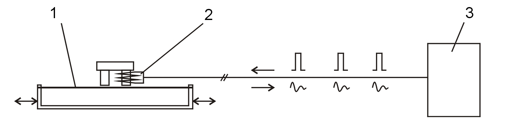
Fig. 2 Intermittent type vibrating wire for static and quasi-static measurements
| 1 | Measuring wire | 2 | Electromagnet |
| 3 | Receiver |
The measuring wire is excited at variable intervals by a d.c. pulse from the receiver. Measurements are taken while the wire is oscillating. The measured values are shown at appropriate intervals (e. g. 1, 2, 4 or 8 sec) at the receiver.
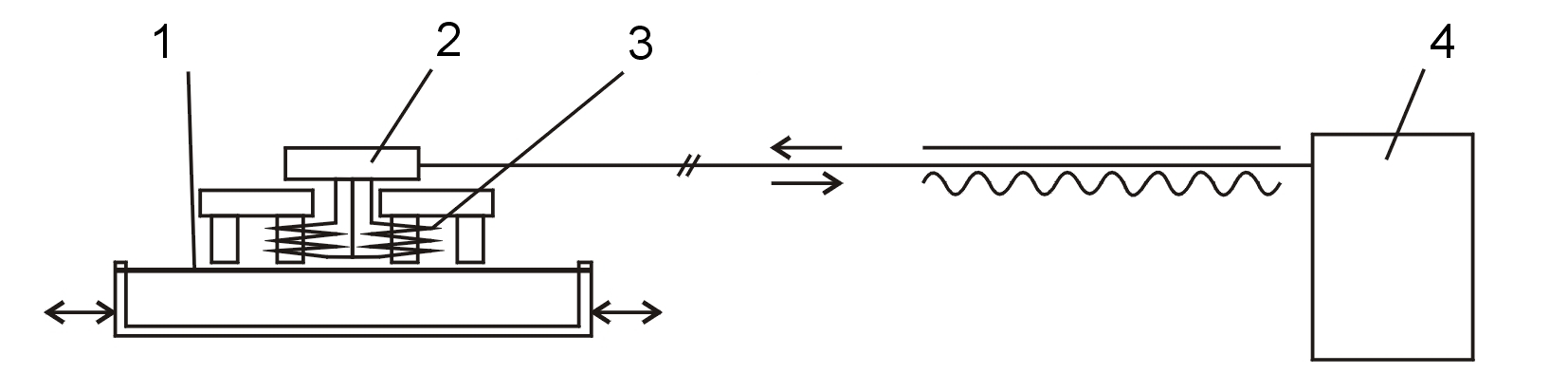
Fig. 3 Continuous type vibrating wire (for static and dynamic measurements)
| 1 | Measuring wire | 2 | Oscillator |
| 3 | Electromagnet | 4 | Receiver |
The continuous type vibrating measuring wire is positioned in an oscillator circle that is fed by the receiver. The system contains two electromagnets: One (the exciter) excites the measuring wire continuously, while the other (the generator) absorbs the induced oscillations continuously. This frequency is measured continuously at the receiver.
Special strain sensors able to cope with construction site conditions have been developed for taking strain measurements on the surface of steel and concrete components as well as for embedding in concrete.
A further way to take strain measurements is to use a high-precision inductive displacement sensor in the form of a pressure/displacement transducer. These sensors achieve a level of resolution that is practically equivalent to that of a strain foil gauge. Furthermore, they are particularly well suited for large strain displacements. A typical example of strain sensors of this type with a measuring basis of 0.5 m to 1.0 m is the INDEX sensor, which is used in concrete piles for loading tests as well as in tunnels and dams.
When measuring stresses in concrete, further uncertainties are added to the evaluation by strains in the concrete that have nothing to do with stresses (shrinkage, temperature strains) on the one hand but which are connected with time-related stress (creep) on the other hand. It is usually impossible to even roughly assess the magnitude of these concrete strain components for stress measurements on structures, which means that they cannot be eliminated from the results (Franz, 1958).
For many years, therefore, stress measurements have been carried out with hydraulic pressure cells which are cemented in the component. Provided the cell has the right shape, the change of pressure in the cell's liquid contents corresponds directly to the change of pressure in the component. The length and elasticity of the cell in the direction of the stress to be measured plays a major role when embedding an hydraulic pressure cell in an elastic medium. If a long cell is more rigid than the surrounding material, the pressures from a large area will be concentrated on the cell (Fig. 4.1). If the cell is softer than the surrounding material, the pressure lines will turn away from the cell into the surrounding area (Fig. 4.2). Hence in the one case the cell gives too high a reading of the stresses, and in the other case too low a reading. For practical purposes it is impossible to equip a cell with the same elastic properties as those of the surrounding material, so the only way to eliminate this fault is to reduce the height of the cell. In the extreme case of an embedded disk, its elasticity is no longer relevant.
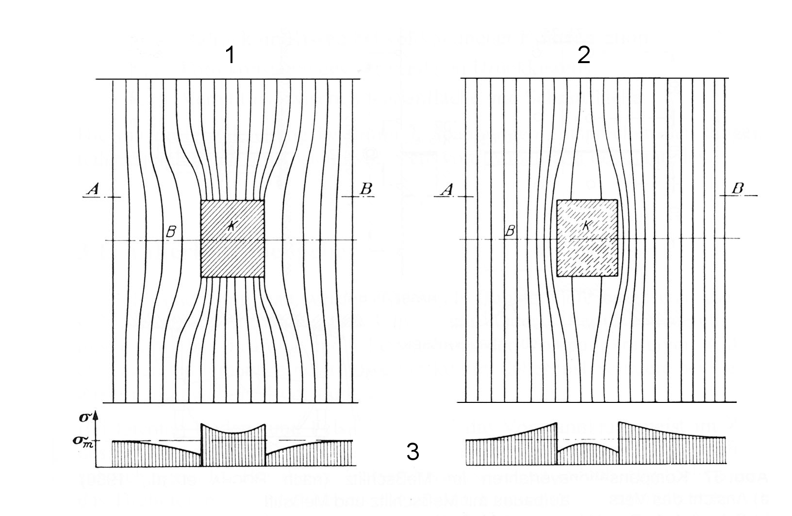
Fig. 4 Compressive stress trajectories in the area of an embedded cell (Franz, 1958)
1 Ek > Eb Cell body more rigid than concrete
2 Ek < Eb Cell body softer than concrete
3 Stresses in section A-B
One possible drawback with this type of stress measurement is the shrinkage gap that normally forms between the hydraulic pressure cell and the concrete in which the cell is embedded. Steps must be taken, therefore, to fill this shrinkage gap or the cell itself before taking measurements, so that the cell sits snugly against the concrete. A further point to remember is that pressure cells of this type always record the total pressure, i. e. the mechanical stress of the component plus, for example, the hydraulic pressure existing in the pore spaces.
If stress measurements are required in components where no strain sensors or hydraulic pressure cells were installed beforehand, a compromise solution is to take compensation measurements. With this method it is only possible, however, to measure stresses at the outer edge of the component.
Artificial stress-relief is induced in the component with a saw cut and the resulting deformation is measured simultaneously. This deformation is reversed again by applying compensation pressure with suitable loading devices. The stresses needing to be induced in this process are usually equivalent to the original stresses.
The compensation method was first used by Mayer et al. (1951) and later simplified and refined by Rocha et al. (1966). Its principle and procedures are illustrated in Fig. 5. As the first step, measuring pins are cemented on the surface of the component in an appropriate arrangement on both sides of the planned cut. The distances between the pins are recorded by electric displacement sensors or set strain transducers (reading accuracy ± 1 mm).
Following the zero measurement, a slot normally measuring 400 mm wide and 5 mm high is cut with a diamond-tipped circular saw. A crescent-shaped hydraulic pressure cell is inserted exactly into the slot and connected with an hydraulic pump fitted to a precision manometer (class 1.0). Finally, the pressure cell is loaded until the relief-induced deformations are compensated for.
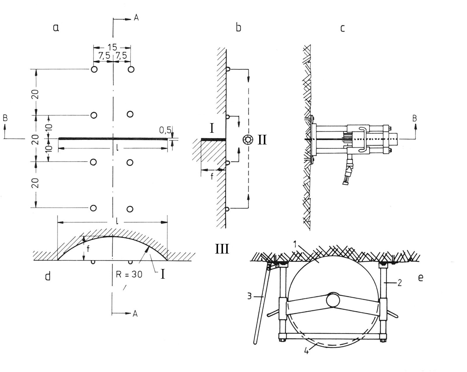
Fig. 5 Compensation method in a measuring slot (according to Rocha et al., 1966)
a) View of the test setup with slot and pins
b) Section A-A. Pressure cell and pins for measurement of deformation
c) Slotting saw dowelled to the measuring point
d) Section B-B. Width of slot = 400 mm
e) Slotting saw: (1) Diamond saw blade, (2) Guides, (3) Lift and lower device, (4) Guard box
I Pressure cell
II Deformation measurement
III Dimensions in cm
The evaluation of test results obtained by the compensation method is based on the following equation:
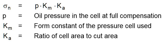
The stresses determined with this equation correspond to the tangential stresses at a distance of 5 cm from the outer edge of the component.
The complete description of Forces and Stresses can also be downloaded here as a pdf.