More than 40 years have passed since, with all due urgency, Stini and Müller pointed out the absolute necessity of conducting large-scale tests in engineering geology and rock mechanics. The whys and wherefores of large-scale tests, especially those for determining strength characteristics, have been explained by objective presentations, and it has been proven most convincingly that the mechanical properties of rock can only be established in a large-scale exploration and not in small-scale tests. The reason is that mechanical laws are statistical laws. Material testing only makes sense, therefore, when the respective test body contains a sufficiently large number of sub-bodies (joint bodies). By nature of the discontinuum, the test body must also possess a sufficient size, which must equal at least six average joint spacings in each spatial direction. The dimensions resulting from this law are so big as to virtually rule out laboratory tests for transport reasons alone. This leaves the in situ test as the only option.
In spite of all the educational work done up to now, large-scale tests for the in situ testing of rock strength are still rare and unpopular. Only a few engineers and geologists use in situ tests consistently and regularly in spite of the fact that in-site testing techniques are now significantly better and cheaper, that they can now be shown to produce good results, and that many objects could not have been built at all without such tests. It seems that they still hope to calculate the mass strength of a rock from the elements substance strength and fissure friction.
The problem of representativeness arises with in situ tests the same as with the taking of samples for the laboratory. When test results are evaluated in stability verifications and calculations, a system of classification is indispensable. It is advisable, therefore, to stage the tests in such areas as may be deemed representative for specific rock strength classes. This classification cannot be undertaken by the rock engineer on his own, nor by the engineering geologist; it needs to be drawn up jointly by both because it has to take just as much account of the structure's statics and safety requirements as of the ground's structural conditions and principles of rock mechanics. It also assumes that the homogeneous areas are closely studied as regards their rock and structure.
Since Leopold Müller and his assistants conducted in situ triaxial tests during construction of the Kurobe Dam (Japan), these tests have belonged to the standard repertoire of in situ tests. Either the test specimen is removed from the rock and then subjected to a genuine triaxial test with hydraulic cylinders or, as a variation, the specimen is loaded triaxially with hydraulic presses and the mean and smallest main orthogonal stress is applied by small flat jacks (see Fig. 1 and 2).
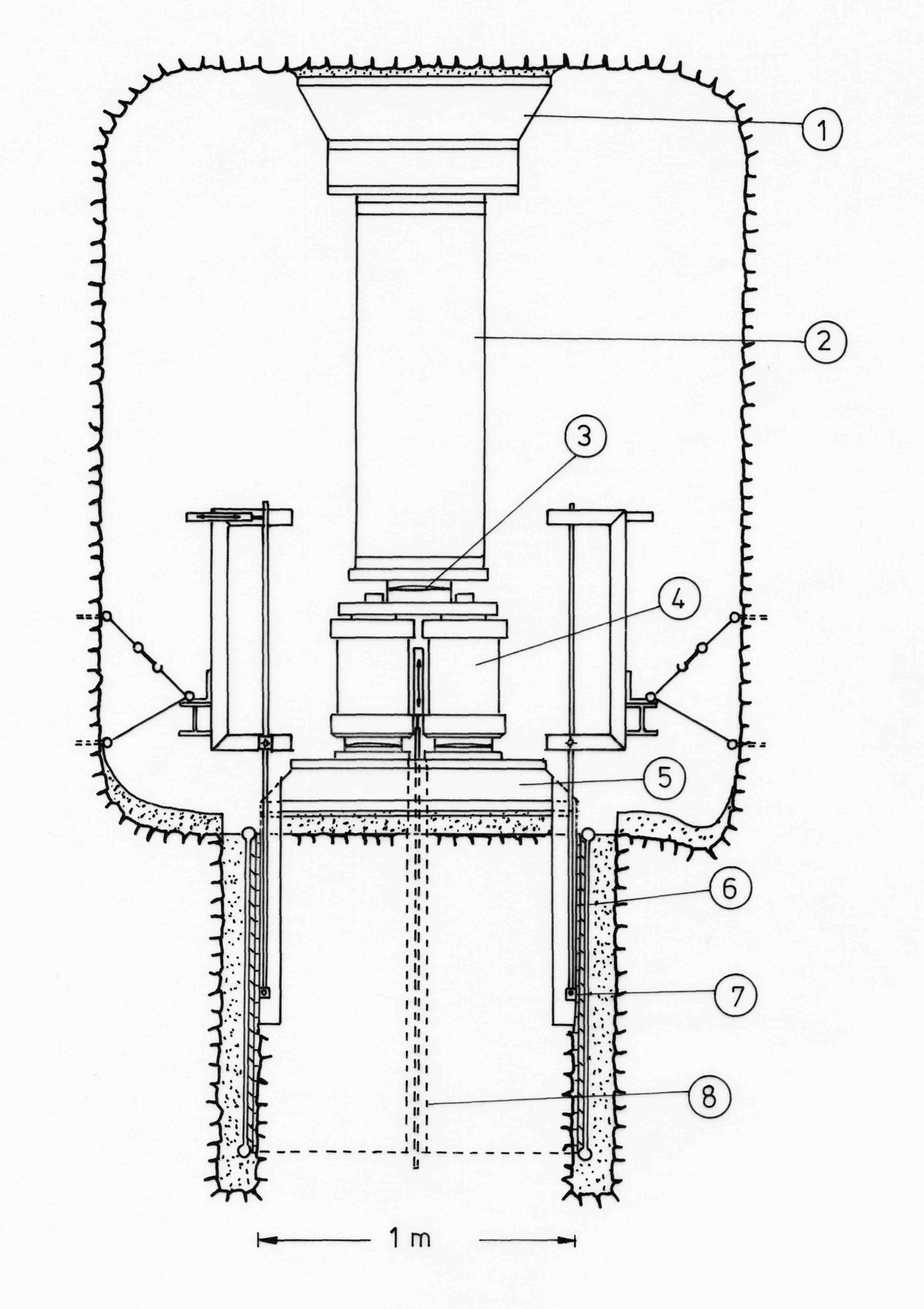
Fig. 1 In situ triaxial test on a specimen of 1 x 1 x 1 m
1 Abutment in the ridge of the test gallery
2 Reaction beam
3 Spherical seat
4 Three pressure cylinders à 1.5 MN
5 Load distribution plate
6 Small flat jack with a maximum pressure of 100 bar
7 Horizontal displacement gauge
8 Vertical displacement gauge
The slot for the small flat jacks is drilled with the help of a slot boring device (Fig. 3), the jack is inserted and the remaining cavity filled with cement mortar. The flat jacks can be loaded with 100 bars and more. Deformations of the specimen in the direction of the mean and smallest main orthogonal stresses are measured by one deflectometer each, which are incorporated in a borehole inside the specimen. The deformations in axial direction are recorded at the load distribution plate by four electric displacement transducers.
Deformation moduli and Poisson's ratios can be determined in the various directions by measuring the deformations in all three of the specimen's orthogonal directions of axis using deflectometers and extensometers, and by measuring the boundary stresses (small flat jack pressures, pressures from press forces). Being able to control the loads in each of the three directions of axis separately permits various states of stress to be created in the specimen.
With the help of the above mentioned displacement instruments it is thus possible to study the deformation behaviour of the anisotropic rock specimen under changing states of stress. Stresses and strains are obtained as representative values for the specimen centre. The surface loads applied to each full side of the specimen guarantee that the state of stress exists at least in the vicinity of the specimen centre, whose main axes correspond with the three directions of the loadings. It can be assumed with acceptable accuracy that distortions of the induced state of stress arise only in the corners of the specimen.
Of all the tests discussed in the remaining sections, none is better suited than the triaxial pressure test for obtaining characteristic values for calculations based on numerical methods. It is possible, namely, to derive not only strength values (the material's limit condition) but also stress/strain correlations from this test.

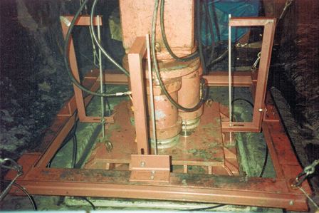
Fig. 2 Axial application of load with three hydraulic cylinders
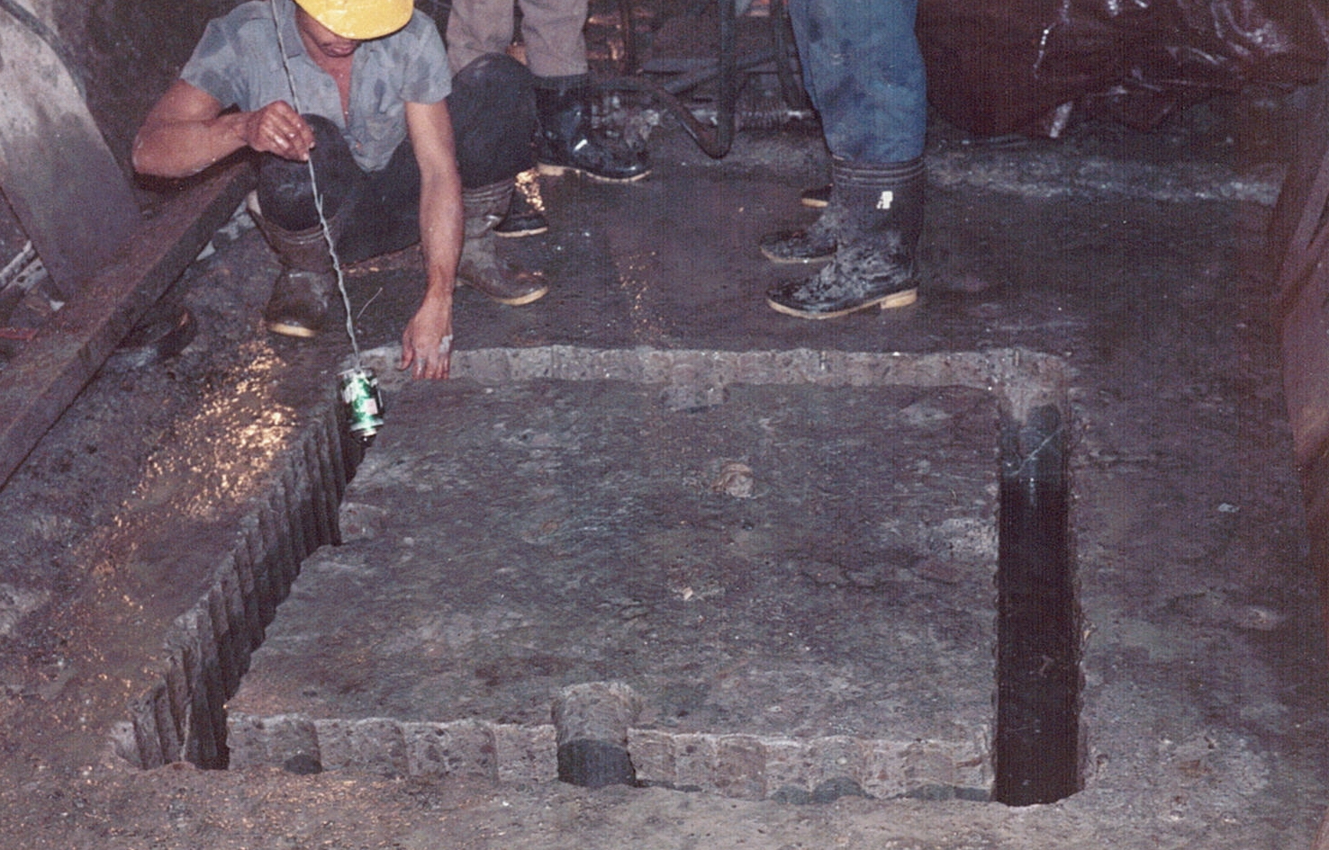
Fig. 3 Slotting the specimen by boring hole to hole
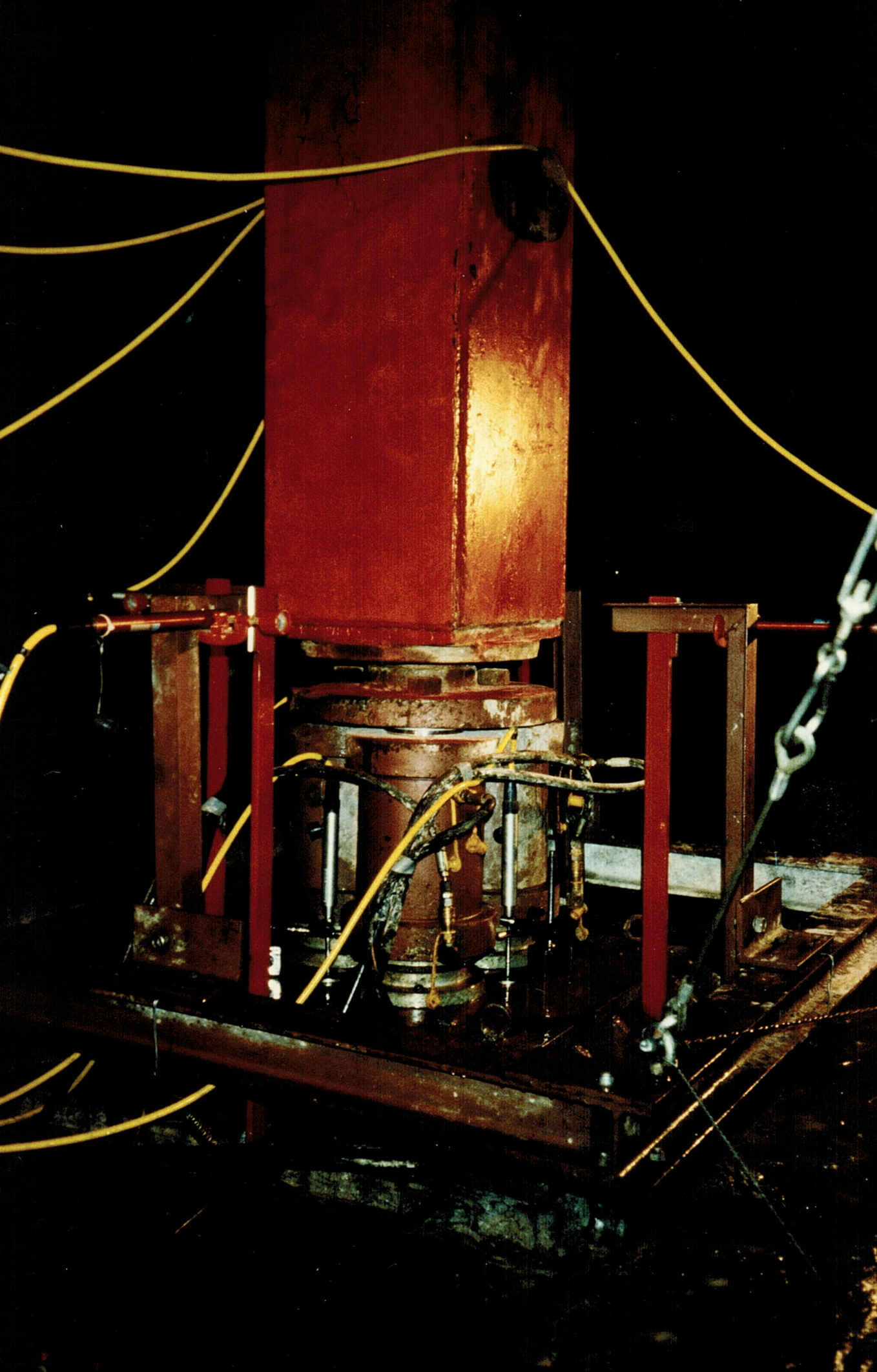
Fig. 4 Triaxial test in the access gallery of the cavern Cirata, Indonesia
The complete description of In Situ Triaxial Tests can also be downloaded here as pdf.