Dilatometer
The flexible dilatometer is generally used for conducting static load tests on in-situ rock in order to determine its stress/strain characteristics. The tests are carried out with the help of a cylindrical, radially expandable probe at freely selectable points inside a borehole ( 101 mm). The probe’s diameter equals 95 mm.
The advantages of an in situ method of this type lie in being able to determine a foun¬dation's characteristics in the practically undisturbed state, whereas laboratory tests usually measure only the maximum values of select specimens.
The measuring system (see Fig. 1) consists of the actual probe with three displacement transducers each set at an angle of 120 ° to the others, a cable reel for holding the com-bined measuring and pressure line, a pressure generator and the measurement electronics.
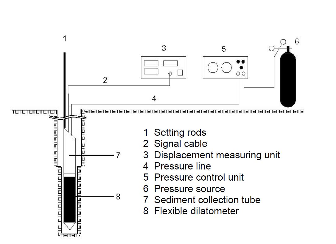
Abb. 1 Schematic representation of the flexible dilatometer setup
Using this test setup it is possible to exert a pressure of 100 bar and more on the bore¬hole wall by pneumatic means. The pressure in the probe is checked with either a high-precision gauge class 0.6 or an electric pressure sensor. The deformation values measured by the displacement sensors are transmitted electrically to a measuring bridge. Thanks to its relatively large measuring range of 25 mm (reading accuracy 0.001 mm), the probe can be used in stiff soil as well as in rock. For special applica¬tions a rod can be used to insert the probe in the borehole properly orientated.
The measuring setup consists of the following individual components:
- Flexible dilatometer probe (dia. 95 mm)
- Calibrating tube made of aluminium (internal dia. 100 mm; length 1500 mm)
- Sediment collection tube, short (length 1000 mm)
- Sediment collection tube, long (length 2100 mm)
- Peg for coupling the steel rope to the sump tube
- Aluminium rod (in lengths of 3 m)
- Pressure line
- Signal cable
- Cable trolley for winding up the bundled measuring lines
- 10 m of connecting line (pressure reducer / pressure measuring unit)
- Displacement measuring unit
- Pressure control unit
- 50 l pressure bottle of nitrogen
- Pressure reducer (pv max. 300 bar; ph max. 150 bar; Qn 150 m³/h)
- Automatic data acquisition
The borehole is loaded during the test in several load cycles; readings are taken of the borehole deformations at each loading stage and the deformations are tracked in each final stage of the loading cycle until they subside. The pressure is then relieved, likewise in stages, with simultaneous measurements taken off the reverse deformation until it stops. The same procedure is followed for the next higher and further load cycles.
The measurement results thus obtained are presented in the form of a diagram that al¬lows for a first assessment of the deformation characteristic.
As a rule the formula for thick-walled tubes according to LAMÉ is used to calculate the moduli of loading and stress-relief:
Loading and stress-relief modulus:
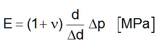
ν = Poisson's ratio
d = Initial diameter of the borehole [mm]
Δp = Pressure differential [MPa]
Δd = Deformation [mm]
The Poisson's ratio used in this formula can be determined by laboratory tests or be taken from suitable tables.
All moduli are calculated as a secant module, i.e. as the difference between two co-or¬dinate pairs in the stress-deformation diagram. The loading modulus thus corresponds to the gradient of the rising section of the stress-deformation diagram and from the 2nd test cycle on it can still be divided into a first and a repeat loading modulus. The modulus of stress-relief corresponds to the gradient of the falling section of the stress-deformation diagram between the points with maximum load and minimum load of the respective stress-relief cycle.
The loading moduli and stress-relief moduli for pressures between 0.5 MPa and 10 MPa can be derived from the measurement results. Since each test is conducted with three displacement sensors concurrently, just a small number of tests are needed to carry out an adequate statistical evaluation or to assess the anisotropy of the rock body in terms of its moduli.
The complete description of dilatometer can also be downloaded here as pdf.
An evaluation example of dilatometer tests can be downloaded here as pdf.