The conditions of friction along interfaces are extremely important for many construction projects in rock. The direct shear test is the established method for determining peak and residual friction because it directly produces a relationship between normal and shear forces and between the corresponding normal and tangential displacements. A further important advantage of direct shear tests is that generally they also permit large shearing displacements.
According to the questions needing to be answered for the construction project, the shear test is conducted either with a constant force and monitoring of dilatancy (normal displacement) or with its prevention and monitoring of the normal force development.
Frictional processes under normal force are found in problems associated with overground construction in rock, e. g. sliding of a monolithic block of rock or wedge. The dilatation required to initiate the sliding process on irregular surfaces is often prevented by the surrounding rock, however, which stirs additional normal forces.
A large number of tests has shown that Coulomb's law can be applied for determining the frictional resistance ts of plane interfaces as a function of normal stress sn. Any irregularities, such as are found at most rock interfaces, will lead however to lifting processes and - under higher normal stresses - shearing processes which exert a decisive effect on the conditions of friction. In such cases it is necessary to consider bilinear or exponential laws of friction.
The mechanical behaviour of interfaces is often complicated in addition by the presence of a rock vein. Where the thickness (t) of the rock vein is small in relation to the amplitude of roughness (T), the shear strength is still determined by the interface characteristics. Tests by Lama (1978) revealed, however, that with a t/T ratio of between just 0.07 and 0.25 the shear strength of clay-filled fissures dropped to 50 % of the value for interfaces without any filling.
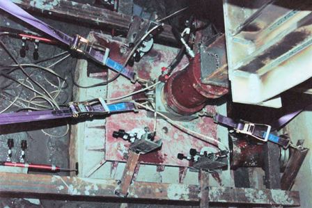
To conduct the test, a block measuring around 300 mm high is etched out of the in-situ rock and surrounded with a square steel frame (dimensions 1000 x 1000 x 300 mm). The joint between the steel frame and the specimen is filled with cement mortar to ensure a close-fitting connection between the frame and the specimen. The surface of the specimen is levelled off with a layer of cement and a pressure distribution plate is placed on top. A steel-reinforced abutment is cast likewise in cement on the side facing the shear force cylinder. The front side of the abutment slopes at an angle of 75 °. When the cement has hardened, the steel abutments for the shear force cylinder are positioned (see Fig. 1).
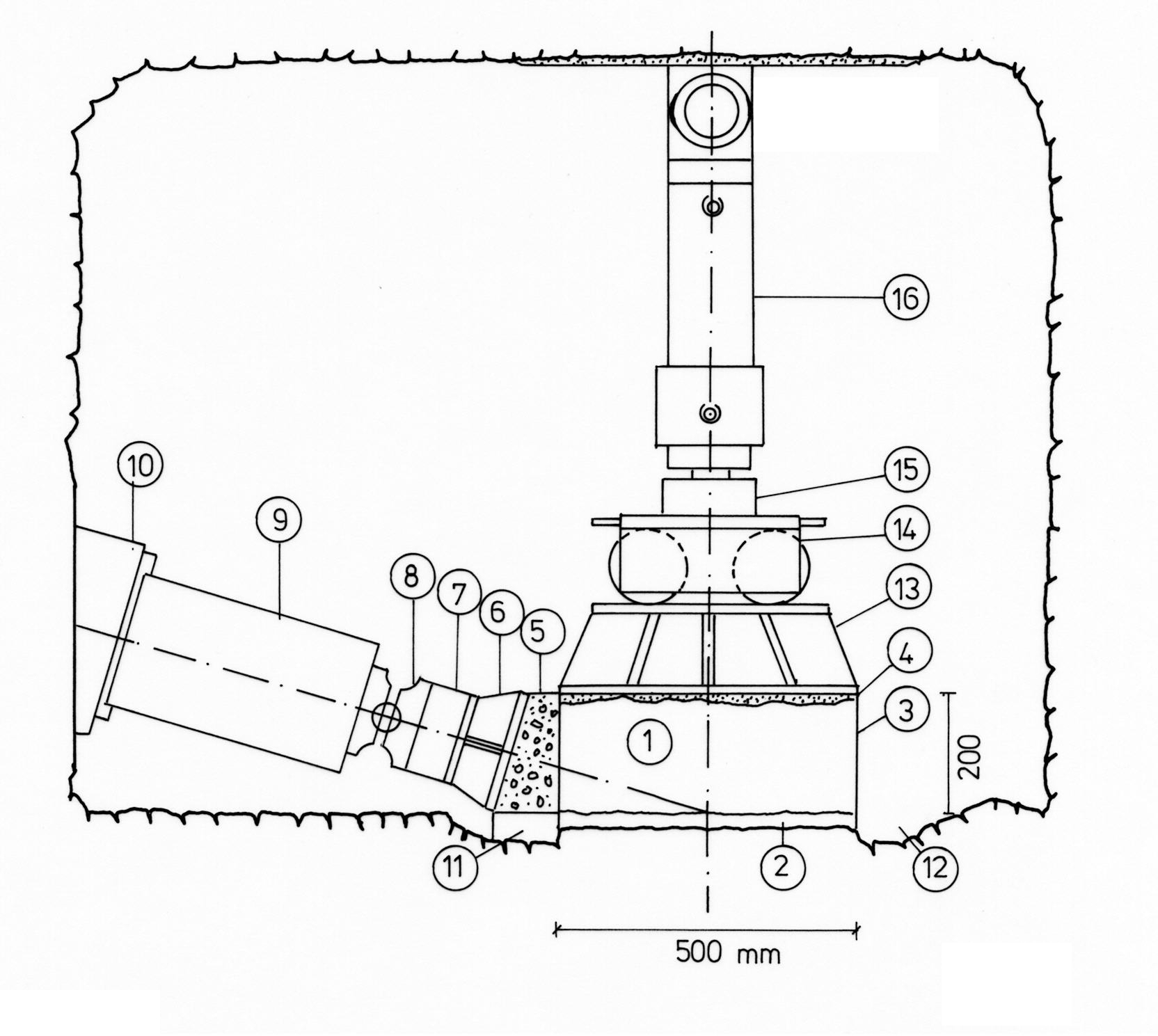
Fig. 1 In-situ shear test on a specimen of 500 x 500 x 200 mm or 1000 x 1000 x 300 mm
1 Test block 9 Jack for 1 MN
2 Shear joint 10 Abutment
3 Jacket made of steel sheet 11 Styrene
4 Levelling mortar 12 Drainage ditch
5 Abutment 13 Load distribution plate
6 Load distribution plate 14 Roller bearing
7 Load cell 15 Load cell
8 Ball joint 16 Jack for 0.2 MN or 1 MN
Normal force is applied against either a dead weight or an artificial or natural abutment (see Fig. 2).
The shear force cylinder is installed at an angle of 15 ° to the shear plane so that the extension of the cylinder axis meets the anticipated shear plane in the specimen's lateral axis. The shearing force is applied to the specimen via a pressure distribution plate.
Eight displacement sensors record the specimen's vertical and horizontal displacements continually in all test phases. The normal force and the shear force are determined via the jack pressure or by load cells. A data acquisition system saves the measured values and shows the stress-deformation diagram online on a screen.
Normally the tests are conducted in several stages. When the probe is properly consolidated, the test is carried out in four stages under constant normal force. In the 1st stage the shear force is reduced upon reaching peak friction, and in 2nd stage it is raised again under the same normal force until the residual friction value is reached. In both the 3rd and 4th stage the normal force is raised and, after brief consolidation of the test block, sheared until the residual friction value is reached.
To hold the normal force constant, with each shear force raise the normal force components resulting from the diagonally acting shear force is taken into account at the normal force cylinder.
The test results are evaluated in accordance with Recommendation No. 4 of Working Committee 3.3 - Rock Testing Technology - of the Deutsche Gesellschaft für Geotechnik e.V. (Henke and Kaiser, 1980) or ISRM Suggested Methods for Determining Shear Strength (1974), i.e. the shear strength parameters j and c are read off the shear stress / normal stress diagram. In addition to allowing for dilatation it is also recommended to plot the results of at least three shear tests in a corresponding shear stress / normal stress diagram and to draw the connecting line as a shear gradient for the condition
![]()
If the plotted results produce points scattered around a straight line, you should use the method of the smallest squares to obtain a straight line.

Fig. 2 Direct shear test on the bottom of a shaft (Triest, dry dock)
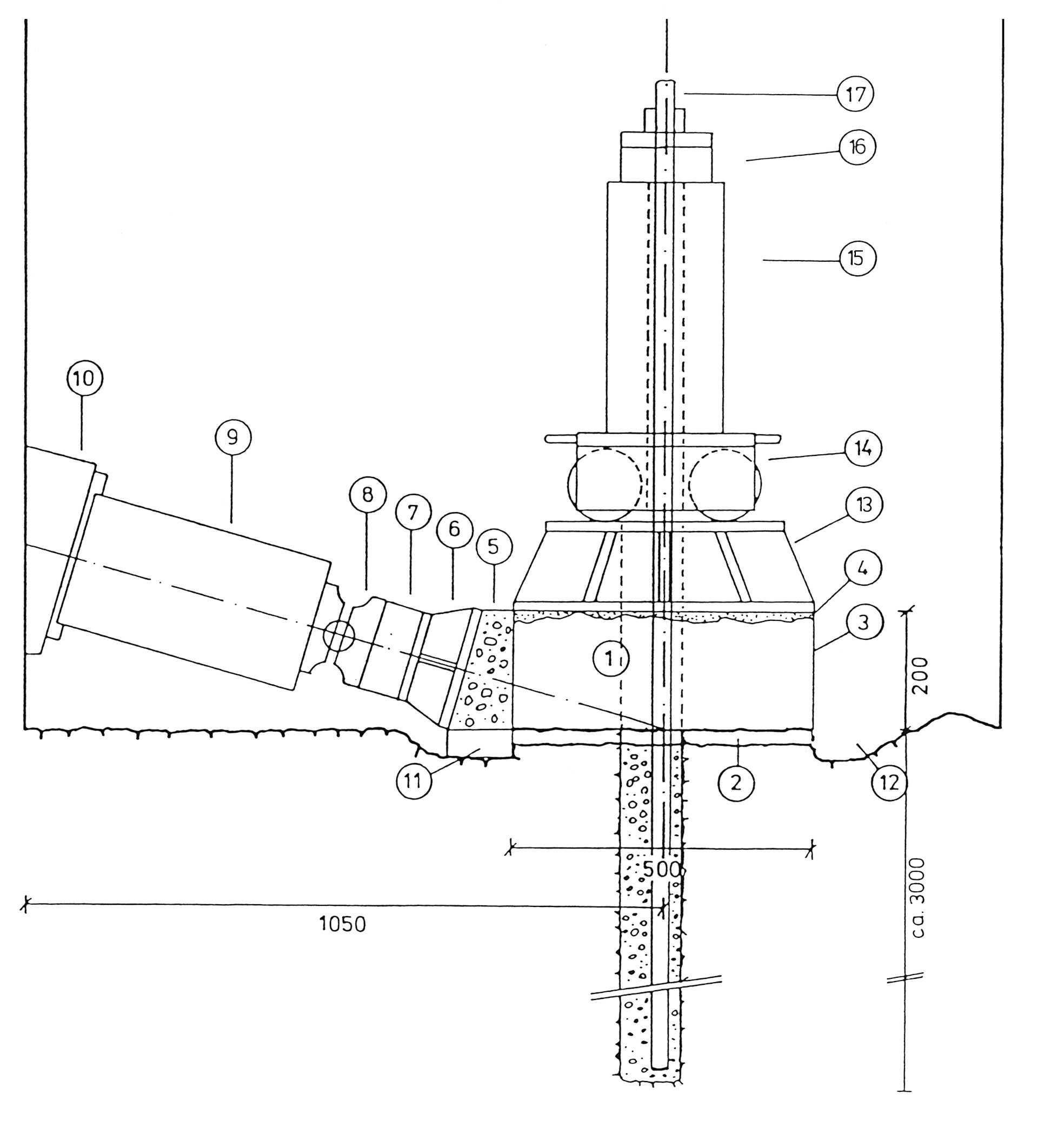
Fig. 3 In-situ shear test. Test variant with rod anchor
1 Test block 7 Load cell 13 Load distribution plate
2 Shear joint 8 Ball joint 14 Roller bearing
3 Sheet steel jacket 9 Jack for 1 MN 15 Jack for 0.5 MN
4 Levelling mortar 10 Abutment 16 Load cell
5 Abutment 11 Styrene 17 Anchor rod
6 Load distribution plate 12 Drainage ditch
The detailed description of In Situ Shear Tests can be downloaded here as pdf.