Ettlinger borehole jack (DE EN ISO 22476-7)
The Ettlinger borehole jack (ESDS) is a borehole probe that uses two cylindrical loading plates to subject the in-situ rock to a uniaxial load in perpendicular direction to the bore¬hole axis. There are two versions of the borehole jack device for use in boreholes with a minimum diameter of 146 mm or 101 mm. The Ettlinger pressure device ESDS l/146 is a further development of the Stuttgarter borehole jack, the only unchanged feature, however, is the geometry of the cylindrical loading plates.
The ESDS I/146 probe consists of two cylindrical shell segments (Fig. 1) with a projec¬tion width of 126 mm and length of 195 mm, i. e. each has a projected load surface of 0.02457 m². The loading shells have articulated bearings and can be pressed hydraulically up to 50 mm apart by means of two pressure cylinders.
Fig. 1 Ettlinger borehole jack ESDS I/146: Loading shells, cylinders and displacement transducers
Probe ESDS I/146 can exert a pressure of over 6 MN/m², which is more than enough to test the modulus of deformation of soils and low-strength rock. An electric transducer measures the displacement of the loading plates at their centre axis as the overall rela¬tive displacement of the two plates. The connections for the electronic and hydraulic lines are accommodated above the probe head in a tube 540 mm long. This tube is connected in upwards direction to a 1200 mm long sump tube, which accommodates a fixture for an orientation rod and an eye for attaching a steel rope (Fig. 2).
Fig. 2 Ettlinger Seitendruckgerät ESDS I/146 mit Sumpfrohr
The borehole jack, which has a diameter of max. 144 mm when retracted, is inserted with a winch into the borehole of 146 mm diameter and, if required, is positioned in depth and operating direction using an orientation rod attached to the probe.
The length of the Ettlinger borehole jack ESDS l/146 is deliberately kept to just 195 mm in order to be able to investigate the often thin layer elements to be found in soils and soft rocks (SMOLTCZYK and SEEGER, 1980). In monotonous rock series, on the other hand, there is an advantage in using pressure plates which theoretically are best if they are of an infinite height. So as not to forgo this advantage, we can also supply the Ettlinger borehole jack with plate lengths of 490 mm (ESDS II/146) (see Fig. 3). This variation is made possible by having the load on the pressure plates generated by cylinder modules, which are attached to the 195 mm high probe, and by replacing just the pressure plate with one of the required length.
The projected loading area of the device ESDS II/146 with a plate length of 490 mm amounts to 0.06174 m².
Fig. 3 Ettlinger borehole jack ESDS II/146: Loading shells, cylinders and displacement transducers
We can also supply a borehole jack for boreholes with a nominal diameter of 101 mm. Like all other Ettlinger borehole jacks its cylindrical shell segments have an opening angle of 120 °. With a projection width of 87.5 mm and length of 490 mm, this particular probe ESDS 101 has a projected loading area of 0.04287 m². The loading shells can be pressed apart hydraulically from 96 mm to 136 mm by means of four pressure cylinders. A maximum pressure of more than 5 MN/m² can be exerted on the surroundings.
With all Ettlinger borehole jacks, the lateral pressure is specified by the test engineer and checked by electric pressure transducers. Contact pressure at commencement of the test usually equals 50 kN/m². The load is applied in stages. As a rule it is sufficient to hold each loading stage for two minutes and then read off the shell displacement. Additional interim readings are taken to establish time-related deformation behaviour.
Using the theory of elasticity, the modulus of sub grade reaction Kss is derived from the test as a device-specific parameter, which can be used in turn to derive a modulus of elasticity or deformation. The probe's range of application covers soil, rocks of alternat¬ing strength, and low-strength rock.
The test is normally conducted with three loading and stress-relief cycles, the maximum pressure of the first and repeat loading cycles being duly coordinated with the rock burden or requirements of the planned structure. The maximum load is reached when the probe's capacity is exhausted or when there are signs of soil failure in the development of the stress-deformation diagram.
According to the used device, the diameter of the test borehole must be at least 146 or 101 mm throughout. In the test zone the borehole diameter must not exceed 156 or 111 mm. If the upper section of the borehole is secured with casing, the internal diameter of the casing must likewise equal at least 146 or 101 mm throughout.
The borehole must be stable. If it is inclined to cave in, the borehole wall must be secured, e. g. by introducing a thixotropic stabilising liquid. The length of the uncased test zone must be at least 1 m. The borehole wall in the area of the testing point should be disturbed as little as possible. After the test is completed, the borehole is sunk to below the next test point and the casing is extended accordingly.
If there is water in the borehole, the borehole deformability test cannot be started until sedimentation of the wet drillings is more or less completed.
It takes between two and four hours to conduct a standard test, including installation and removal of the probe, depending on the depth of the test.
The measured data logged during the borehole jack test are evaluated by a data proc¬essing system, and the test results are presented in two forms:
- Graphic presentation of stress-deformation diagrams;
- Tabular overview of the measured data plus the characteristic values calculated from this data.
The stress-deformation diagrams (Fig. 4) show a more or less pronounced bend under low lateral pressures, depending on the consistency of the borehole wall and rock. In range I, contact between the loading plates and the soil is still incomplete. In range III there are signs of the borehole failing in the loaded area. Range II represents the linear-elastic range of the stress-deformation diagram; only this range complies with the test evaluation principles.
The stress-strain state induced in the rock by the loading was investigated by SEEGER (1980) on the basis of the theory of elasticity and, with the help of a spatial finite ele¬ment study (BUCHMAIER and SCHAD, 1982; REIK and XING, 1993), was calculated numerically.
The following relationships apply:
Where:
d = Initial diameter of test borehole
f = Instrument-specific factor according to FE calculation
Δd = Borehole expansion in the load interval
Δp = Lateral pressure in the load interval
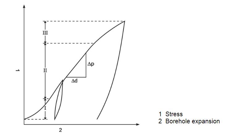
Fig. 4 Typical stress-deformation diagram of a borehole jack test
The following instrument-specific factors f apply for the borehole jack ESDS I/146 with the above mentioned dimensions, according to the Poisson's ratio of the rock:
for v = 0,25 f = 0,792
for v = 0,30 f = 0,785
for v = 0,40 f = 0,749
In our evaluation (see attachment), the loading and stress-relief module is calculated for each load cycle. In the loading branches the first loading modules and the repeat load¬ing modules are distinguished. Where "XXXXXX" is printed in the tabular overview in¬stead of a numerical value, the calculation produced an infinitely large modulus of deformation. This is the case when the change of displacement of a load interval is v = 0,000 mm. A deformation modulus EB = 0 , on the other hand, when the stress-deformation diagram runs horizontally, i. e. when continuation of the displacement as a function of time was measured under the same lateral pressure.
The older test-setups for borehole deformability tests were also evaluated with the theory of linear elasticity. KÖGLER simplified the mechanical state further still into a uniaxial state of stress, to which he applied HOOKE’S law. MÉNARD uses the solution derived from the theory of elasticity for a thick-walled cylinder, whose outer radius approaches infinity, i. e. a uniform state of deformation. There is a certain illogic in this, however, because
- either the state of deformation really does extend over a large range, in which case the assumption of a uniform state is unjustified,
- or the displacements are restricted to a sufficiently small range, in which case you cannot apply the solution for an infinitely thick cylinder.
The fact that a range III is clearly measured during borehole jack tests indicates that the former assumption is the more correct of the two.
When designing the Stuttgarter borehole jack, SEEGER (1980) dispensed from the outset with creating a pseudo-uniform state. Instead the three-dimensional state of a pair of forces acting symmetrically outwards in a cylindrical opening was calculated for the drained, linear-elastic state of the soil. If the opening was disregarded, it was also possible to draw on the analytical solution, i. e. the integrated MINDLIN solution over a vertical rectangular plate. If, on the other hand, the opening was taken into consideration, preference was given to the finite element method, which is very reliable for linear-elastic problems.
Depending on the coefficient of lateral contraction, the FE calculations in the linear-elastic infinite mass (connection with tensile strength in the vertical plane of symmetry) or semi-infinite mass (plane of symmetry without tensile strength) produced a required load of between 15.8 kN and 29.4 kN to achieve a displacement of 1 cm. The modulus of elasticity of the continuum equalled 5000 kN/m². When the ruling probe dimensions are applied, we obtain the instrument-specific factors f, as we called them above.
The following instrument-specific factors f apply for the borehole jack II/146:
for v = 0,25 f = 0,960
for v = 0,30 f = 0,949
for v = 0,40 f = 0,898
The weak dependence of the function P(n) on the Poisson's ratio previously noted by GOODMAN et al. (1968) was confirmed by SEEGER: P increased with n in accordance with the increasing constancy of volume, the greatest increase taking place with the in¬finite mass solution, i. e. 14 % in the transition from v = 0.30 to 0.40.
GOODMAN et al. give the following formula for the evaluation of their borehole jack tests:

where
d = Initial diameter of the test borehole
K = Stress factor as a function of the central angle ß of the load and of the Poisson's ratio v
The stress factor K can be taken from the following table:
| β | ν = 0,30 | ν = 0,40 |
| 60 | 1,152 | 1,080 |
| 70 | 1,200 | 1,129 |
| 80 | 1,225 | 1,159 |
| 90 | 1,232 | 1,170 |
| 100 | 1,224 | 1,169 |
| 110 | 1,204 | 1,156 |
| 120 | 1,155 | 1,088 |
It is known that an evaluation based on GOODMAN et al. (1968) fails to produce satisfactory results for moduli of over 3000 MPa. In such cases the moduli need to be cor¬rected by the function published by HEUZE and SALEM (1977). The use of borehole jack devices in hard rock is generally problematic, as BECKER (1985) has pointed out.
The complete description of Ettlinger borehole jack can also be downloaded here as pdf.
An evaluation example of Ettlinger borehole jack can be downloaded here as pdf.