The plate load test is performed inter alia in exploration galleries or shafts, but it can also be conducted on the surface by applying dead weights or loading with tension piles. (Loading with the weights of vehicles or similar is usually insufficient, unlike plate load tests on soil.)
Plate load tests in galleries are usually conducted with opposing load plates. Hydraulic cylinders are used to press the two plates against the gallery walls. The loading and displacements of the gallery walls are recorded together with the displacements of fixed points at various distances from the loading plate (in the rock). The required compressive stresses should be approximately double the theoretical vertical stress above the lowest point of the structure, but usually not more than 4 MN/m2.
Assuming that a rigid loading plate is loading a homogeneous elastic semi-infinite mass, the moduli of loading and stress-relief can be derived from the plate pressure/plate displacement curve as mean values over the theoretically affected area of rock:
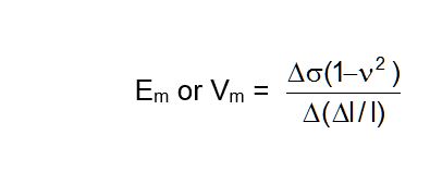
where
Δσ = Change of stress assuming an even distribution of load
ν = Poisson's ratio
Δl = Displacement of the loading plate
l = Depth of action (assuming I = 1.57 times radius of loading plate)
In order to take account of the effect of rock loosening at various depths, deformation moduli (Ed and Vd) are also determined in special cases as a function of distance from the loading plate (gallery wall). This entails using multiple-point extensometers to measure the displacements of various fixed points (3 to 5) in the rock underneath the loading plate, which amounts to measuring the actual depth of action.
From the results it is possible to derive deformation moduli as a function of distance from the loading plate using the following equation:
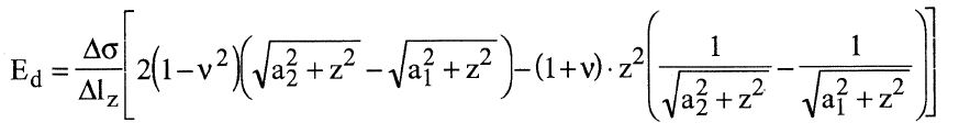
Δlz = Displacement of a measuring point at a distance z from the loading plate (in a central hole orthogonal to the loading plate)
ν = Poisson's ratio
z = Distance of loading plate centre to measuring point
a1 = Radius of the measuring hole in the loading plate
a2 = Radius of the loading plate
By turning the axial direction of the test apparatus it is possible to draw conclusions about the directional dependence of the deformation behaviour. Experience indicates that plate load tests produce smaller deformation moduli than are actually present, a fact reported by Kratochvil (1963) as the result of comparisons with measured settlements at several dam foundations.
If necessary, plate load tests in undersurface cavities can be continued until the gallery wall fails under the load distribution plates. Well defined strength values such as are produced in the single-axis or multiple-axis pressure test are not obtained, however, due to the likely inhomogeneous distribution of stress.
The height of the test apparatus can be adapted to local conditions with spacer elements (see Fig. 2 and 3). In galleries the plate load test can be conducted as a double plate load test in accordance with Recommendation No. 6 of Working Committee 3.3 - Rock Testing Technology - of the Deutsche Gesellschaft für Geotechnik e.V. (1985) and ISRM Suggested Methods for Determining In Situ Deformability of Rock (1978). This entails measuring the rock displacements at both loading plates (Fig. 1).
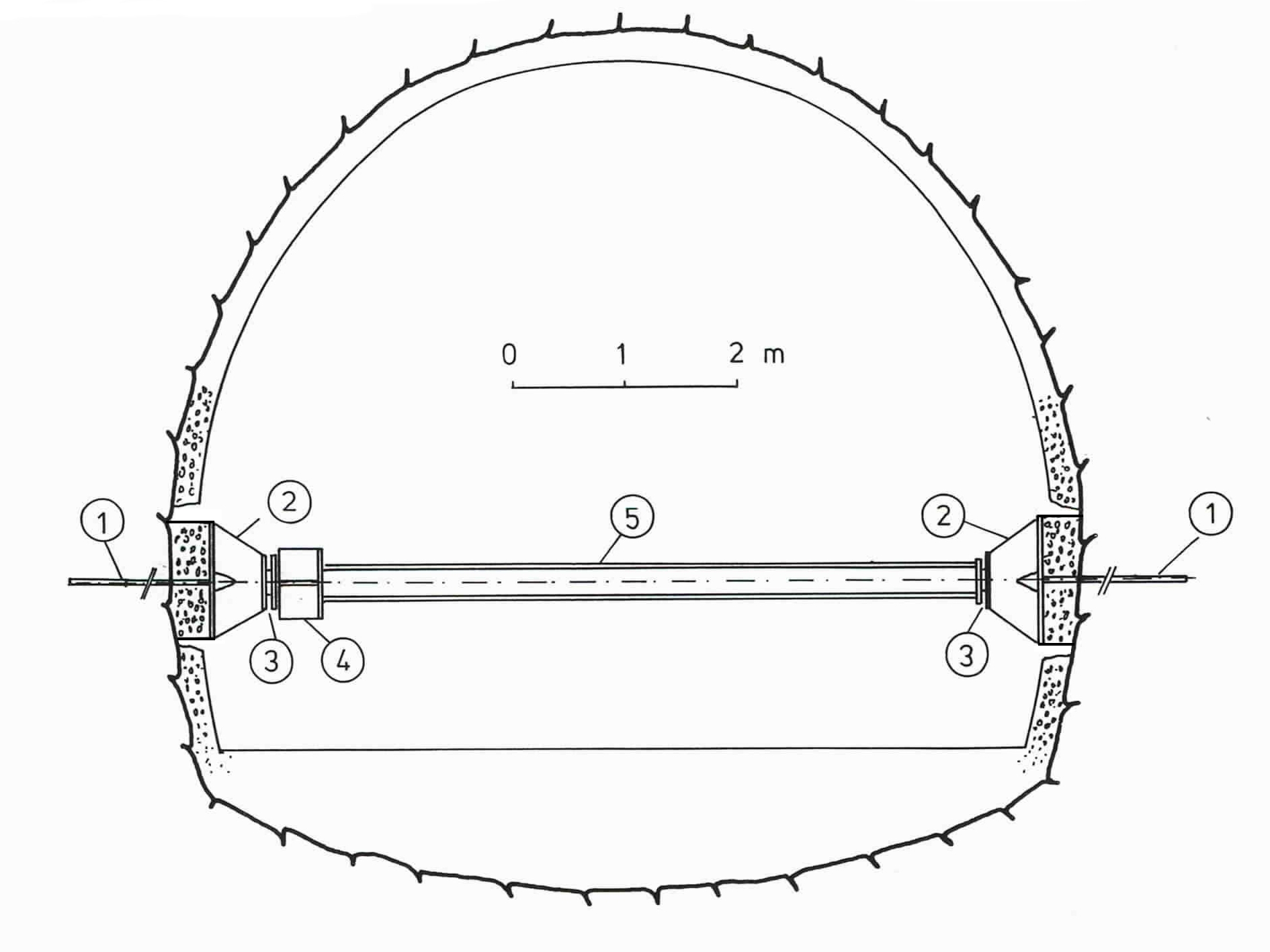
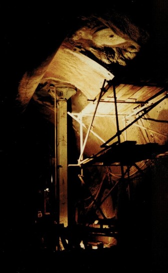
Fig. 1 Plate load test in the access gallery of the Landrücken Tunnel
Performance of a horizontal test.
Test setup shown in schematic form. Loading plate mounted on concrete of the tunnel shell. Extensometer head for displacement measurements at rock/concrete transition.
1 3-point extensometer
2 Load distribution plate dia. 1128 mm
3 Seat
4 Three pressure cylinders à 1.5 MN
5 Reaction beam
Fig. 2 Test setup with loading plate diameter of 798 mm
Fig. 3 Spacer elements for test setup with loading plate diameter of 798 mm
The selection of the loading plate diameter, 798 or 1128 mm, is a question of the scale effect. This means the ratio of specimen size to mean fissure clearance, sufficient and insufficient to record the mechanical regularities (which are statistical laws). Only when the number of the substructures of which the rock mass of a certain dimensional area consists is large enough, the physical relations derived from a test or material test can be considered as statistically valid. Although known for a long time this is unfortunately not yet taken into general account.
Furthermore we would like to remind you that the relations of the scale effect are not continuous but discontinuous functions; a problem early recognised by the rock mechanics research as major in situ tests in the fifties and sixties show, but nevertheless only slowly taken into consideration.
In some structural situations it may therefore be necessary to select a loading plate surface of 3, even 4 m². In such cases it is easier to use the method of the hydraulic pressure cell developed by Kujundzic instead of the plate load test.
The test setup with the hydraulic pressure cell is shown in Fig. 4. At the provided measuring point a slot is made in the rock and a circular pressure cell of 2 m diameter is inserted. The gap between pressure cell and rock is filled with concrete.
When loading by the pressure cell its mean deformation is measured by the volumetric method. For this purpose water or hydraulic oil is pumped from a graduated rising tube into the pressure cell by means of a hand or motor pump. Thus a hydrostatic pressure is produced that is transmitted via the concrete to the rock. This entails a deformation of the rock and at the same time the pressure cell enlarges its volume while the level of liquid in the rising tube sinks.
Fig. 4 Test with hydraulic pressure cell
(1) Slot in the rock, (2) Pressure cell dia 2 m, (3) Concrete filling,
(4) Rising tube, (5) Hand pump, (6) Displacement measuring setup
(in accordance with Kujunzic, 1970)
From the magnitude of this sinking and the known cross sectional area of the rising tube the total change of the pressure cell volume can be calculated and thus the mean rock deformation. Additionally the deformations of the rock can be recorded at the perimeter of the loaded surface with electrical or mechanical displacement sensors.
The modulus of elasticity and deformation can be derived using the following equation of Boussinesq
where
Δp = Total load assuming an even distribution of load in MN
n = Poisson’s ratio
Δlm = mean rock deformation in m
r = Radius of the loaded circular surface in m
To determine the modulus in certain structural situations even a loading plate surface of 3 m² is insufficient to completely ruling out the scale effect. But in our opinion it is possible to produce hydraulic pressure cells of 2.5 m or even 3 m diameter, which equals the surface of 7 m².
For large structures as for example barrages even loading plate surfaces of 7 m² are comparatively small. In these cases we recommend to conduct in situ major tests in one of the exploration galleries for the structure, that means to conduct a radial pressure test or a hydraulic chamber test in accordance with Oberti to obtain an exact and directional entity of the deformation characteristics of the rock.
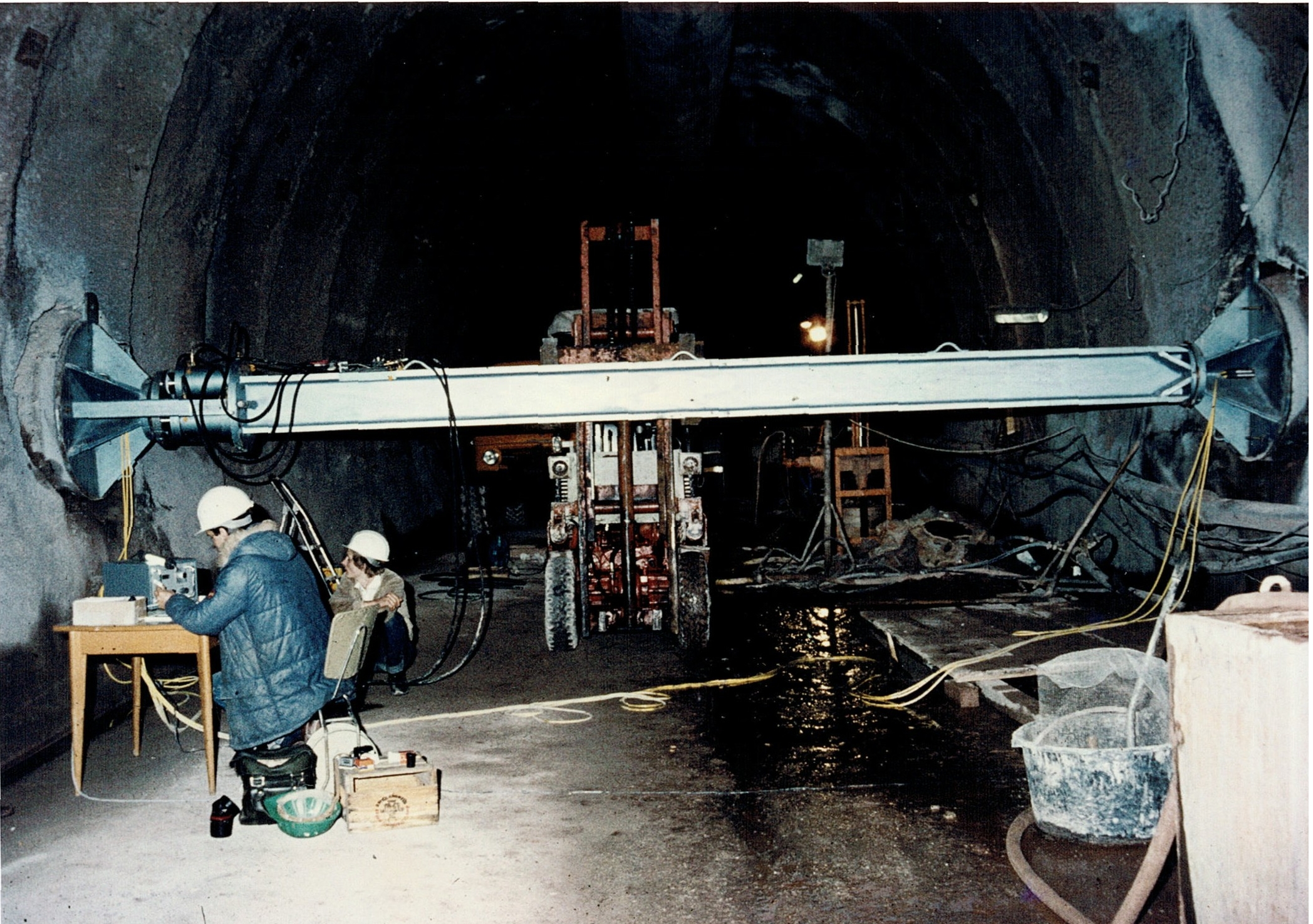
Fig. 5 Plate load test in Landrücken Tunnel, horizontal test
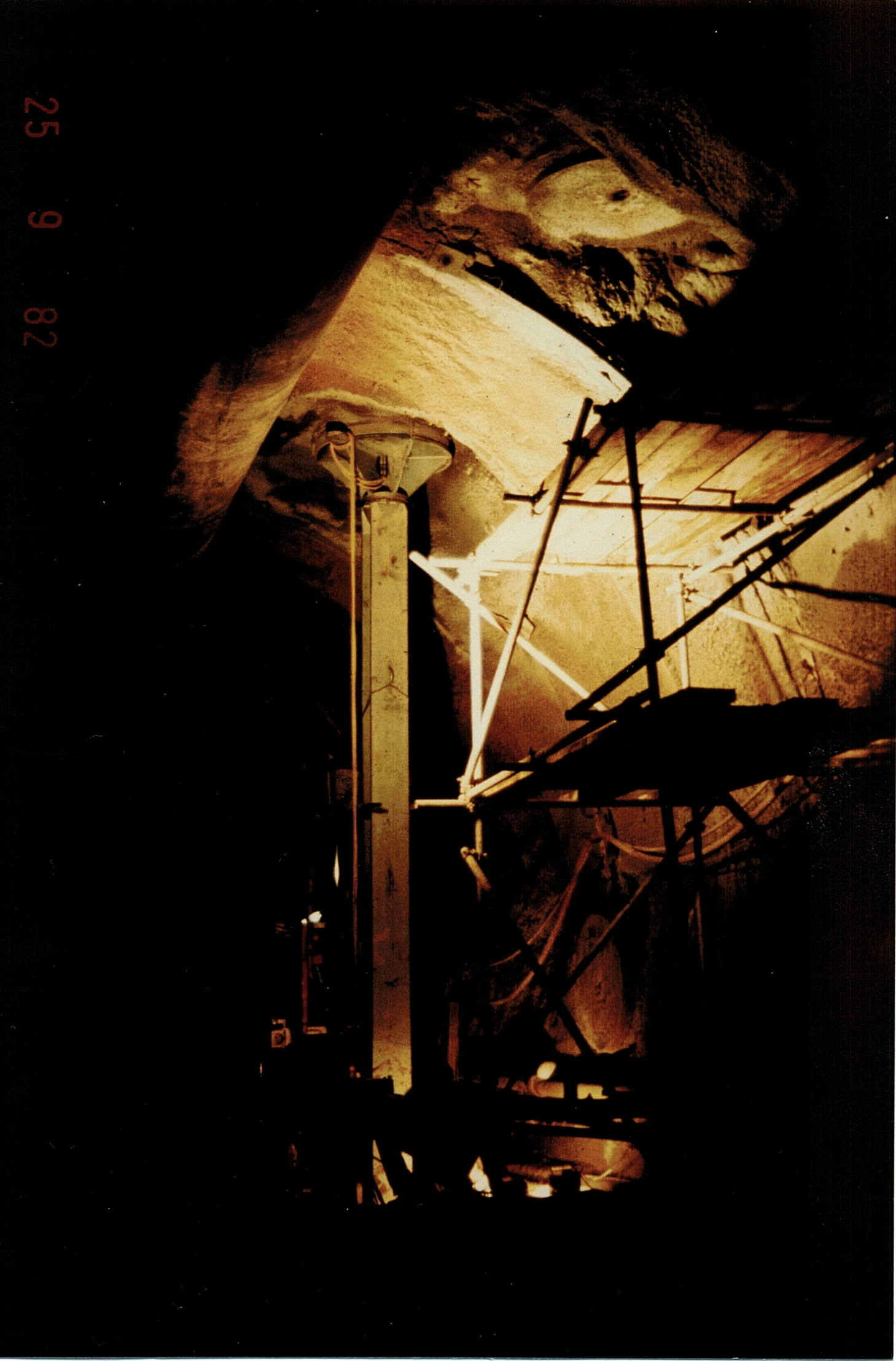
AFig. 6 Plate load test in Landrücken Tunnel, vertical test
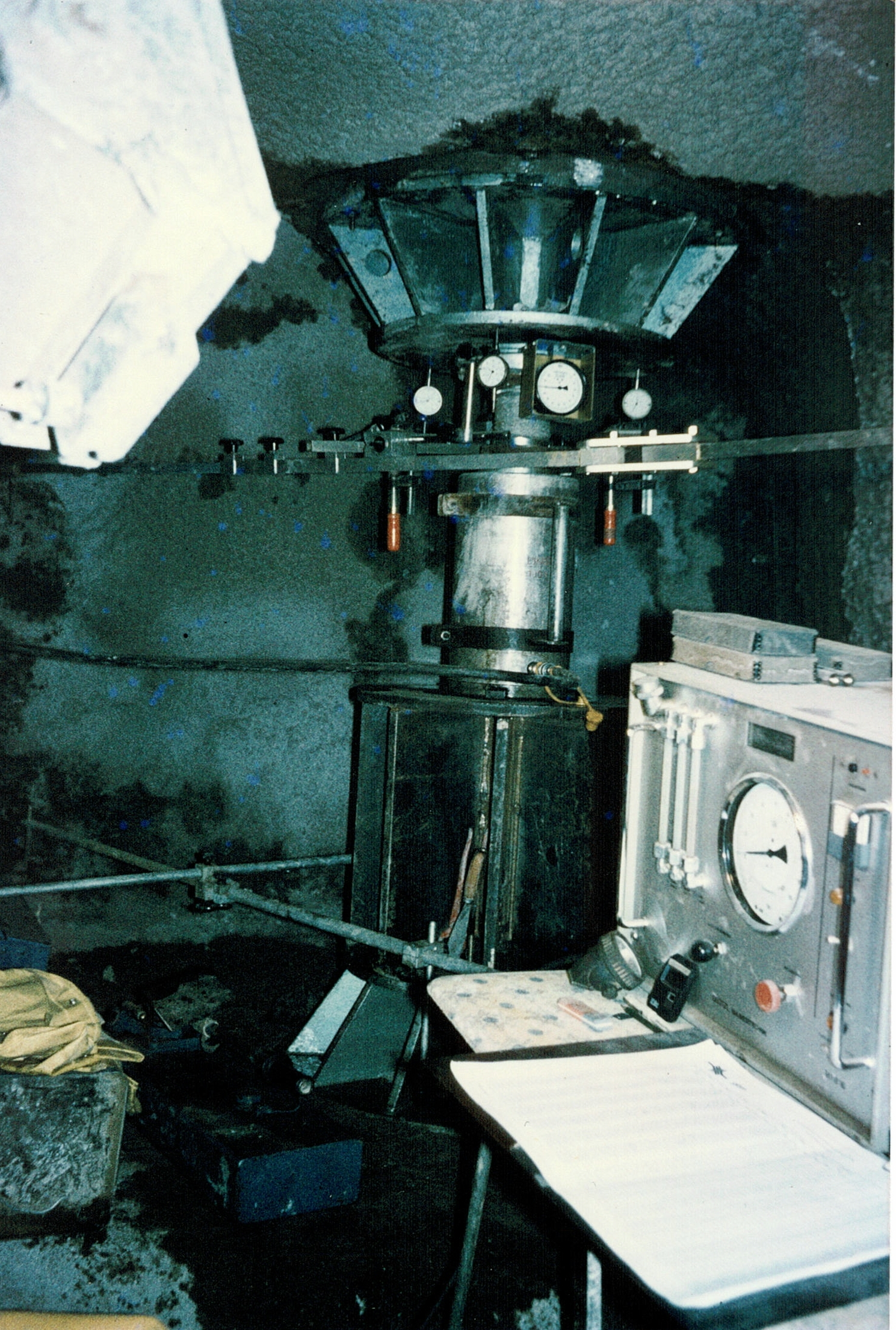
Fig. 7 Plate load test in Rollenberg Tunnel, vertical test
The complete description of Plate Load Tests can also be downloaded here as pdf.