Temperature sensors are used to measure the temperatures arising at built-in measuring elements or components. The results permit corrections to be made in response to temperature changes. Temperature fluctuations at extensometers, for example, can lead to lengthening or shortening of the measuring rod.
The following principles are utilised in the measurement of temperature through contact, with subsequent electrical processing of the measured data:
- Resistance thermometers (PT 100, NTC, …), i. e.:
Resistance as a function of temperature (R = f(T)) - Thermocouples (NiCr - Ni, PtRh-Pt, ...), i. e.:
Voltage as a function of temperature (U = f(T)) - Quartz sensors, i. e.:
Frequency as a function of temperature (f = f(T))
A resistance thermometer consists of
- a measuring resistor, and
- essential installation and connection components, e. g. a protective tube.
It uses the relationship between the electrical resistance of a metallic conductor and its temperature. Resistance thermometers are mostly made of platinum; nickel, copper and - lately - iridium are also used, however.
Measuring resistors are calibrated at 0 ° C to 100 W ± 0.1 W. Resistance generally increases as the temperature rises. It changes in accordance with a specific reproducible series of fundamental values. For platinum and nickel the value series is specified in DIN 43760 of October 1980 and listed in Tables. The operating ranges are:
Nickel 100 (Ni 100): - 60 up to + 180 ° C
Platinum 100 (Pt 100): - 200 up to + 850 ° C
Changes of resistance are transmitted as changes of voltage by copper cables, either directly or via transducers. A certain error results from the line resistance. According to the requirements imposed on accuracy, a distinction is drawn between two, three and four conductor circuits in the type of connection used in the transducer's input circuit (Fig. 1).
With the two-conductor circuit, the connection to the measuring transducer consists of just two cores. Their resistance is in series with the measuring resistor and must be calibrated (as a general rule to 10 W). Changes of resistance in the supply conductors reoccur in the measurement as an error.

Fig. 1 Temperature measurements with the resistance thermometer
1 Measuring resistor
2 Connection terminals
3 Measuring element
4 Internal conductors
5 Supply conductors
6 Output unit
Fig. 1 a) shows a schematic diagram of a two-conductor circuit with a Wheatstone bridge and moving coil element (deflection method), b) a three-conductor circuit with a self-calibrating bridge circuit based on the bridge-zero method, c) a self-calibrating bridge circuit based on the bridge-zero method with a two-conductor circuit and an additional conductor loop, and d) the voltage compensation method with automatic calibration and a four-conductor circuit.
With the three-conductor circuit, the errors caused by changes in temperature of the supply conductor are just about 1/10th of those with a two-conductor circuit.
With the four-conductor circuit, measurements are independent of the conductor resistance over a wide range, and there is no need for the circuit to be calibrated.
A thermocouple consists of:
- a pair of sensors, and
- essential installation and connection components (e. g. a protective tube).
A sensor pair consists of two wires of different metals or metal alloys, which are soldered or welded together at one end (the measuring point).
Certain material pairs have proven particularly successful in industrial applications:
|
Type |
Application Temperature Range | |||
|
Sign |
Code |
|||
|
DIN 43710 |
IEC584-1 |
Letter |
Colour anode |
|
|
Cu-CuNi |
U |
red |
- 200 up to + 900 |
|
|
Cu-CuNi |
T |
brown |
- 200 up to + 350 |
|
|
Fe-CuNi |
|
L |
red |
- 200 up to + 600 |
|
Fe-CuNi |
J |
black |
- 240 up to + 750 |
|
|
NiCr-Ni |
K |
green |
- 200 up to + 1200 |
|
|
Pt13Rh-Pt |
R |
orange |
0 up to + 1600 |
|
|
Pt10Rh-Pt |
S |
orange |
0 up to + 1600 |
|
|
Pt30Rh-Pt6Rh |
B |
white |
+ 600 up to + 1700 |
|
Thermocouples generally display greater mechanical stability than resistance thermometers and have shorter response times.
Any difference in temperature between the free ends of a thermocouple and the measuring point will generate a thermo-electromotive force (Seebeck effect). A temperature differential is always detected, so a reference point with a known temperature needs to be defined. The free ends of the thermocouple (positive and negative legs) are joined in a bipolar connection to a terminal (e. g. a socket in the terminal housing). Equalising conductors are used to extend the sensors from their terminal to a point with as constant a temperature as possible, i. e. the reference point. Up to 200 ° C, equalising conductors are governed by the same fundamental values and tolerances as for the corresponding thermocouples.
The effect of temperature fluctuations at the reference point can be compensated by an equalising circuit, e. g. a compensating box (Fig. 2).

Fig. 2 Connection of a compensating box with a thermocouple and a power pack
1 Equalizing conductor, 2 Thermocouple, 3 Cu conductors, 4 Compensating box
The compensating box is supplied with auxiliary energy from a separate current stabiliser. It contains a Wheatstone bridge circuit that has to be calibrated for a temperature of 20 or 0 ° C. If the reference point temperature deviates from the reference value, the bridge's temperature-related resistor R3 will change. A positive or negative voltage develops in the bridge diagonal and is added to the thermo-electromotive force. A different bridge current is required for each type of thermocouple.
In the output circuit a distinction is drawn between two and four conductor connection methods (Fig. 3).
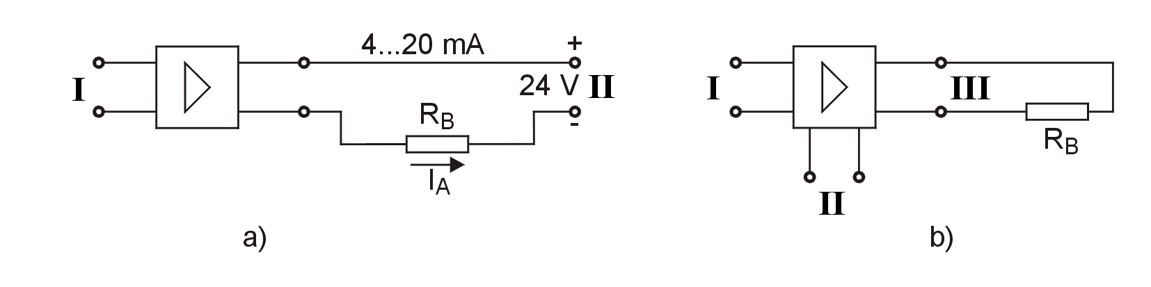
Fig. 3 Temperature measurement with a thermocouple
a) Two-conductor connection method
b) Four-conductor connection method
I Input
II Supply
III Output
With the two-conductor method, the signal emitted by the transducer is superimposed on the input supply voltage. The output signal lies between 4 and 20 mA.
With the four-conductor method, the output signal (current or voltage) is isolated from the supply voltage. There are two conductors for the auxiliary energy and two conductors for the output signal.
With a quartz sensor - yet another possibility for measuring temperature - quartz in the form of a tuning fork is accommodated in an hermetically sealed, gas-filled tube of just a few millimetres in diameter. The resonant frequency of the quartz body, which displays a near-linear frequency/temperature characteristic, is drawn on for measuring purposes. The measuring range for quartz sensors is limited to between – 70 ° C and + 300 ° C. In this range the quartz sensor is superior to the resistance thermometer and thermocouple in very many performance features. This applies in particular to zero point stability, which can be taken as 0.1 ° C / 10 years. Until now the quartz sensor has found little use in geotechnical applications; resistance thermometers or thermocouples are mostly used.
The complete description of Temperature Measurements can also be downloaded here as a pdf.